
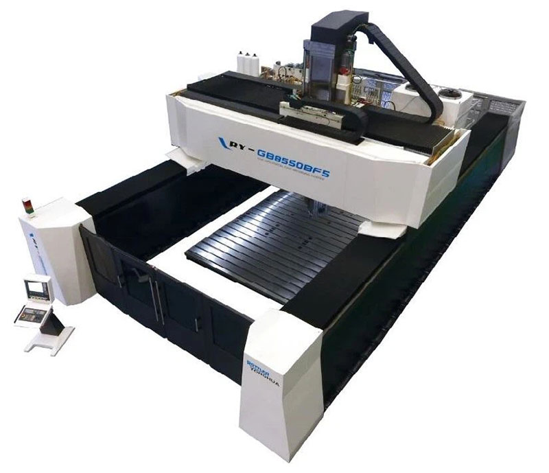
Cross Beam Box in Box Structure Of Gantry Machining Center
 2025-06-29| View:
 Gantry machining center is mainly composed of gantry milling machine beam, column and worktable. The beam is the key component, which directly determines the overall performance of the machine tool. The structural arrangement of the beam has an important impact on the stress state and performance of the machine tool structure, stress peak, structural rigidity, structural stability, vibration resistance and structural fatigue. The beam component structure under current technology adopts the front arrangement of upper and lower guide rails. In this structure, the weight of machine tool sliding saddle and ram and cutting reaction force are all borne by the front of the beam. In order to ensure the rigidity and machining accuracy of the beam, the thickness of the beam and the number of ribs must be increased, but it will increase the weight of the beam. The increase of beam weight will increase the load value and reversing impact when the machine tool moves, and after the increase of beam weight, it will be more affected by gravity. When the beam is very long, there will be obvious sagging, which will seriously affect the machining accuracy. In addition, in order to shorten the distance from the spindle center to the beam, the thickness of the sliding saddle is usually designed to be very thin, which is easy to deform during processing, which is not conducive to the accuracy maintenance of the machine tool. In actual machining, due to the influence of the gravity and cutting force of the workpiece, it is very easy to lead to different degrees of deformation of the beam and affect the machining accuracy of the machine tool.
Cross beam box in box structure comprises a beam body and two parallel guide rails arranged at the upper end of the beam body, and the guide rail is a heavy-duty linear guide rail; The beam body is a hollow cuboid structure, which is composed of two long beams and a side beam connecting the long beam. A row of rectangular grooves are opened at the bottom of the connection between the long beam and the side beam. The guide rail is arranged on the upper surface of the long beam and supported by a strip plane protruding from the top of the side beam. The long beam and side beam are grid structure, and the grid structure of the long beam is evenly arranged rectangular grooves, which are arranged in 3 rows from top to bottom; The upper end of one of the two long beams is provided with a ball screw, which is supported by a column block protruding on the top of the side beam. The side of the long beam is provided with arc fasteners. Both ends of the ram (spindle assembly) are clamped on two parallel guide rails through clamping slots, one end of which is fixed by ball screw, so that the ram can move along the guide rail without deviation.